CLICK HERE to view an instructional video on how to remove your door trims.
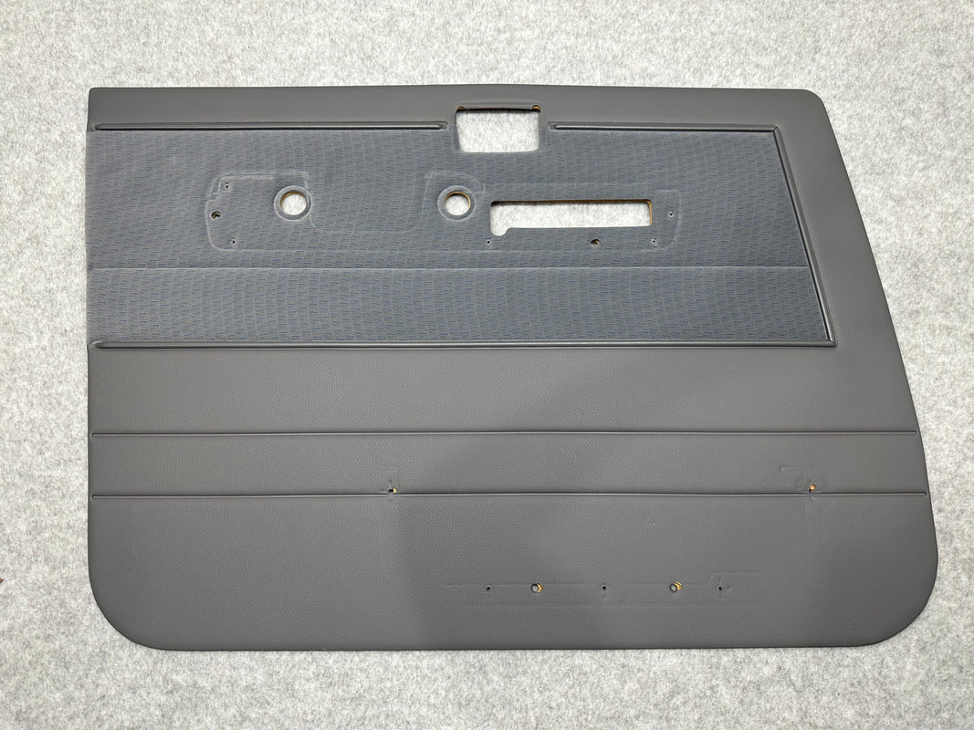
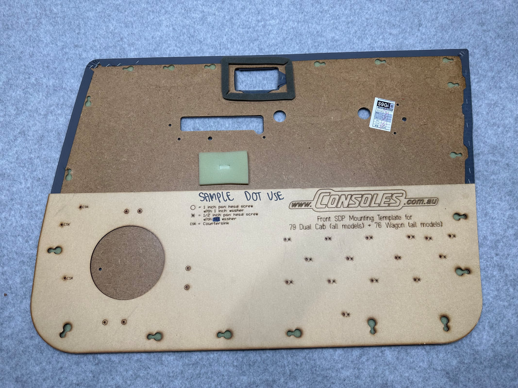
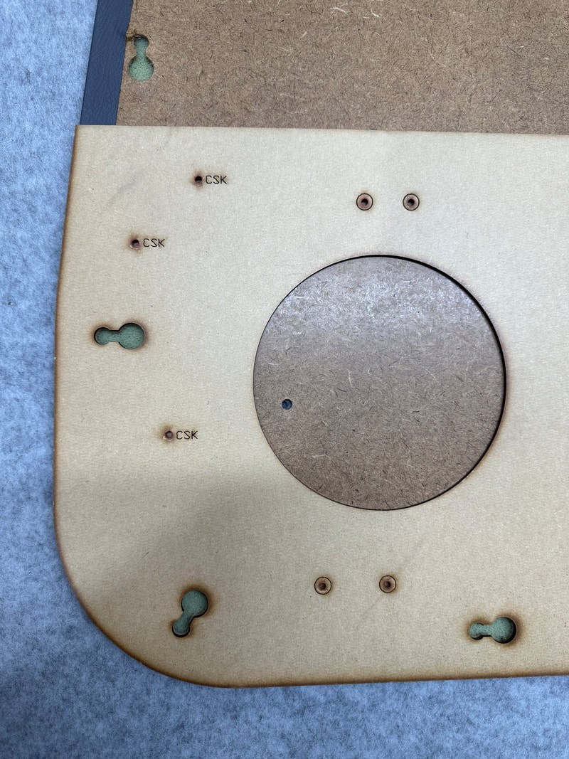
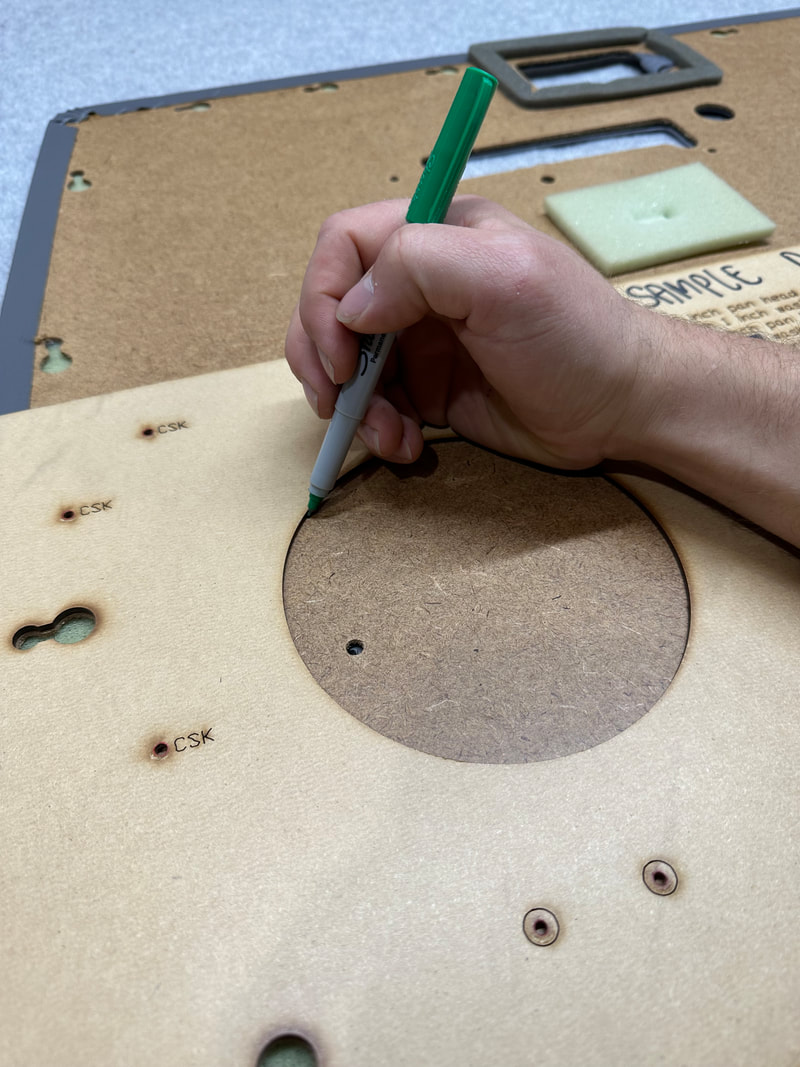
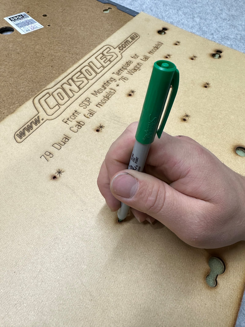
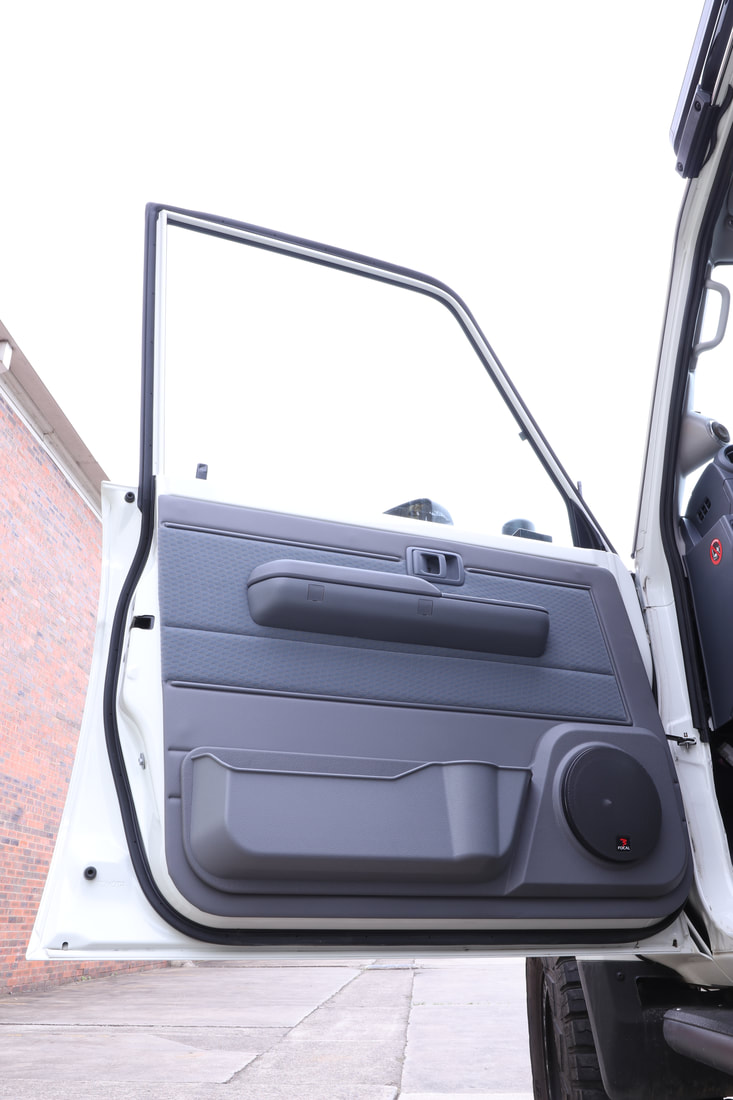
CLICK HERE to view and instructional guide on how to fit your new Speaker Door Pods to your door trim.
CLICK HERE to view an installation timelapse.
CLICK HERE to view and instructional guide on how to fit your new Speaker Door Pods to your door trim.
CLICK HERE to view an installation timelapse.
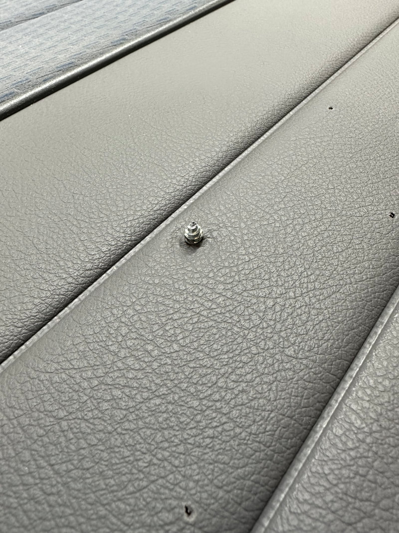
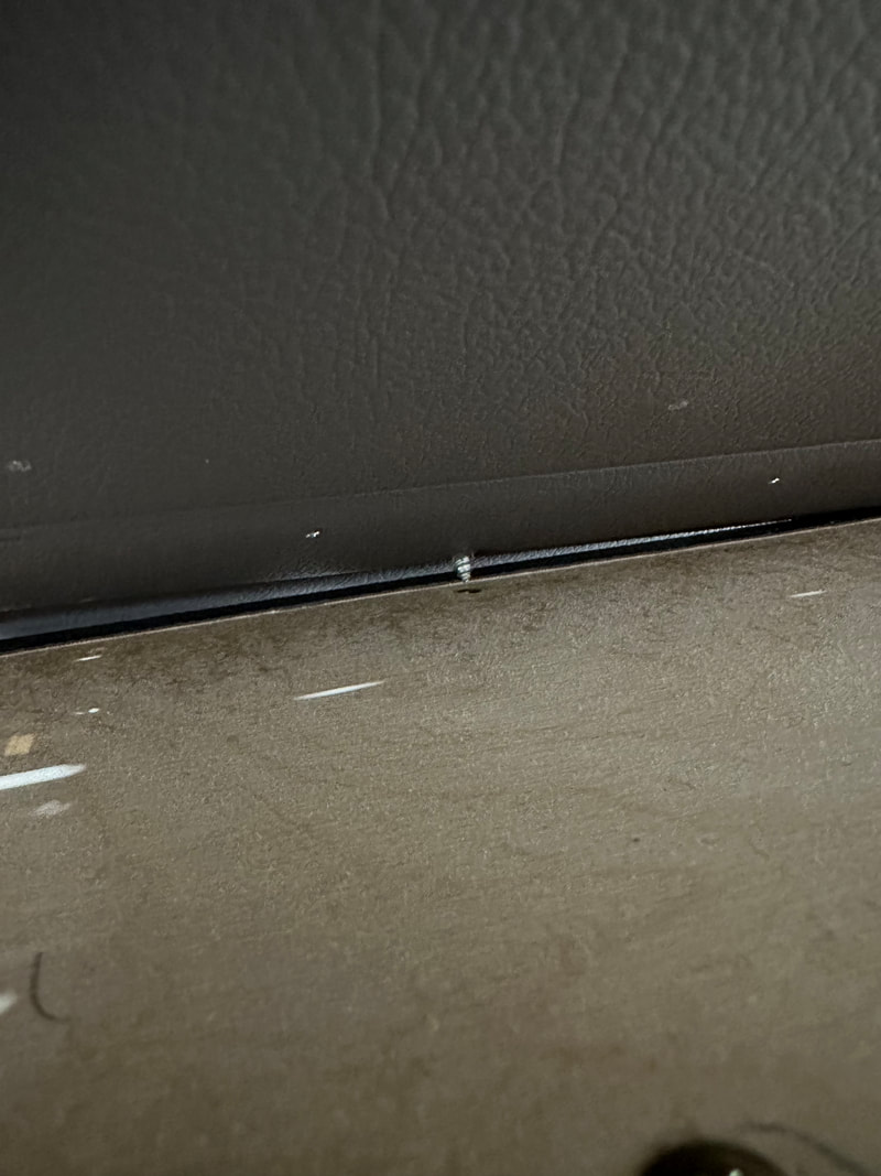
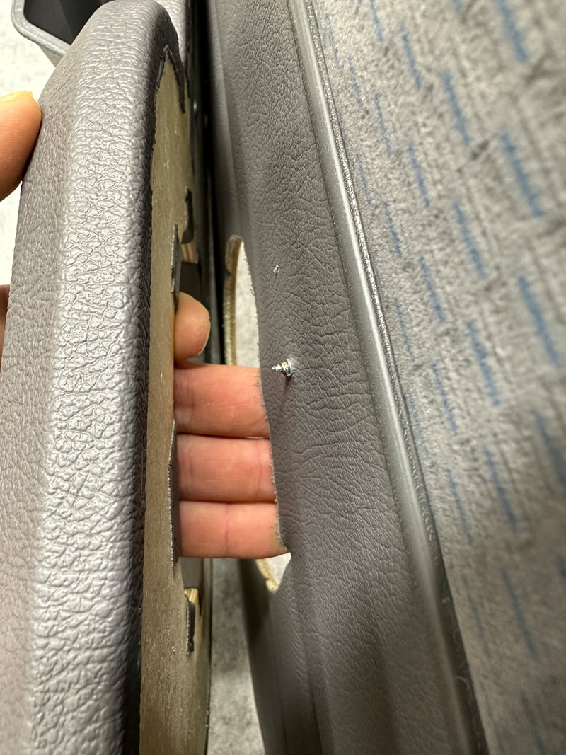

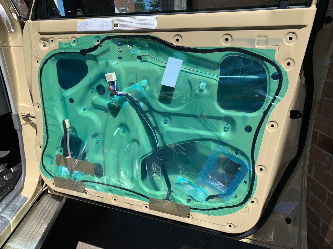
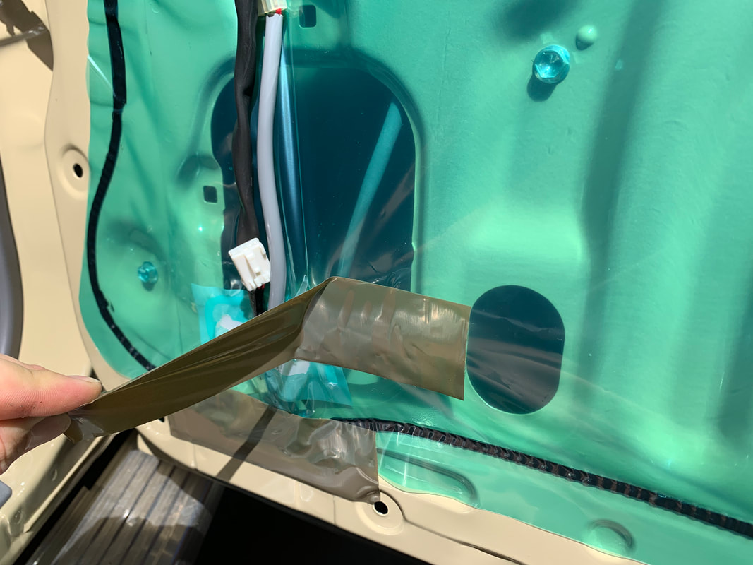
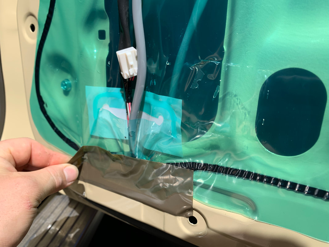
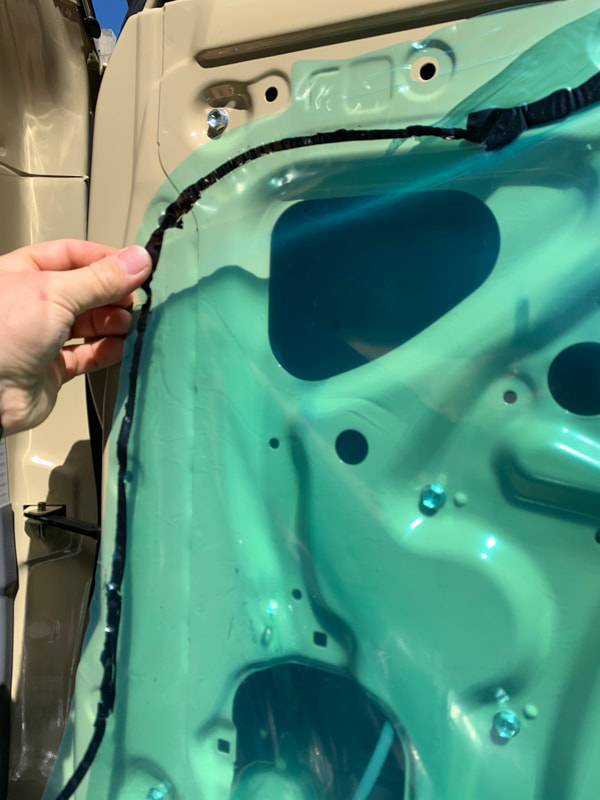
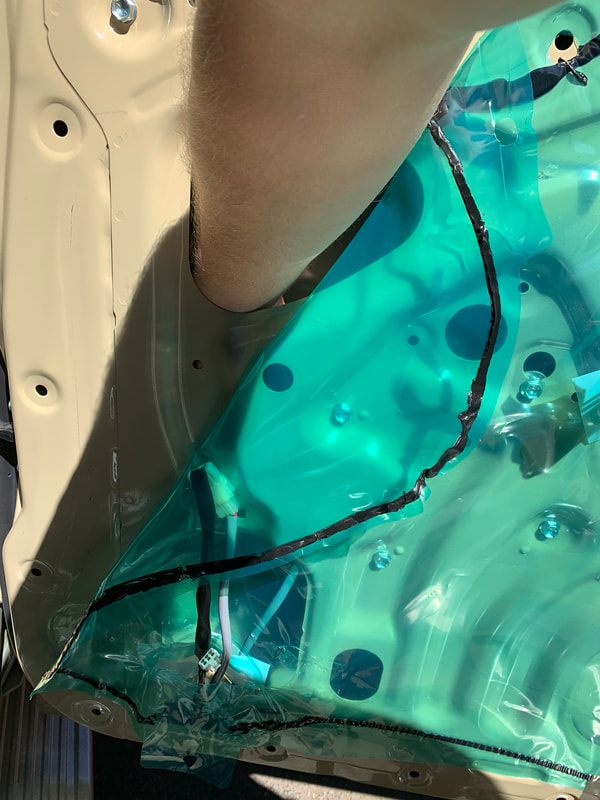
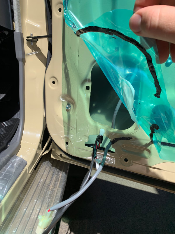
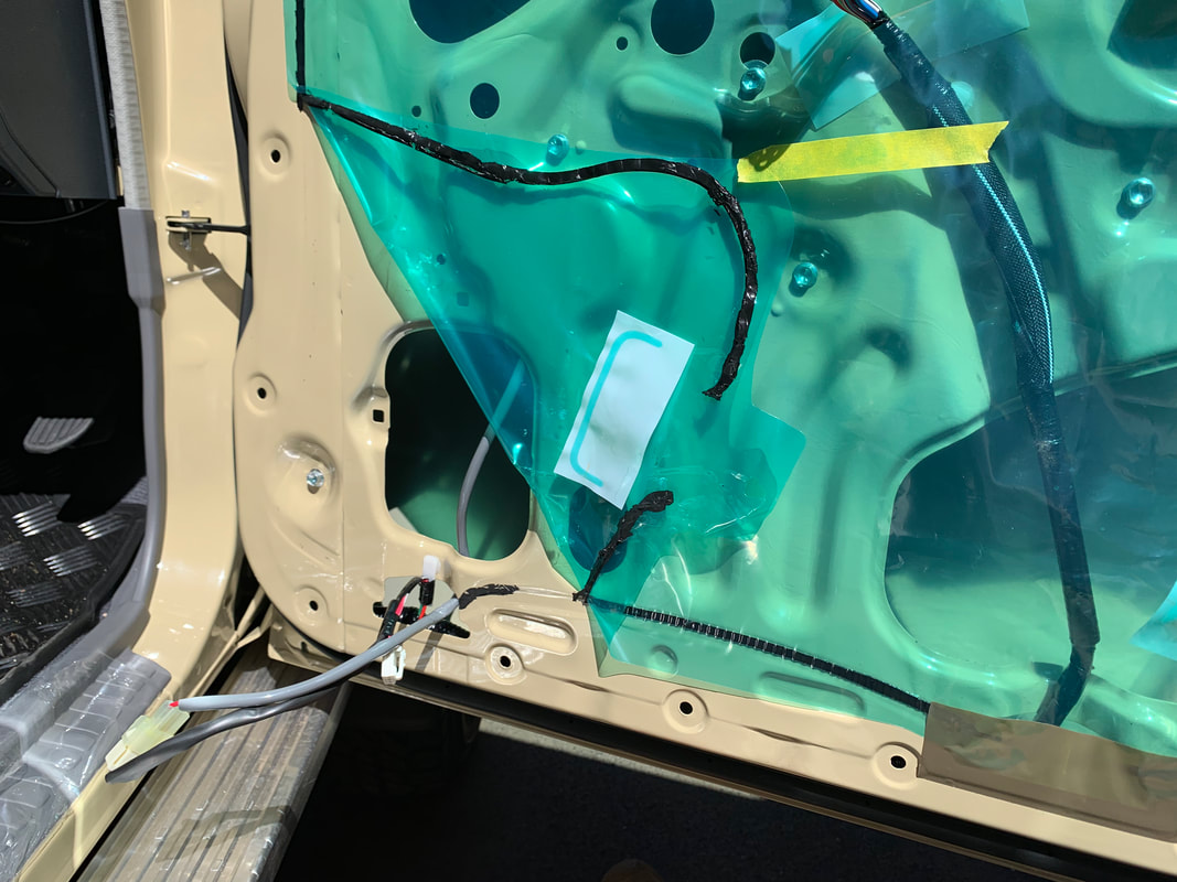
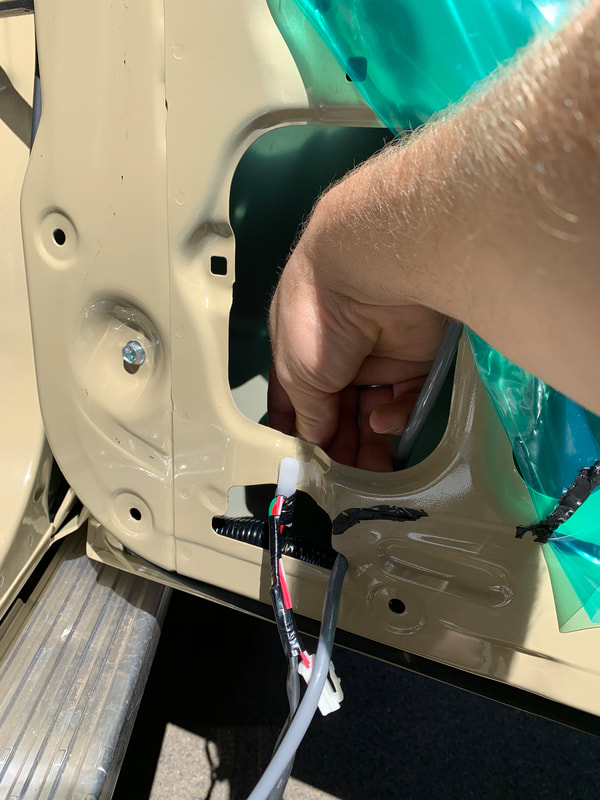
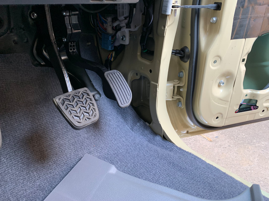
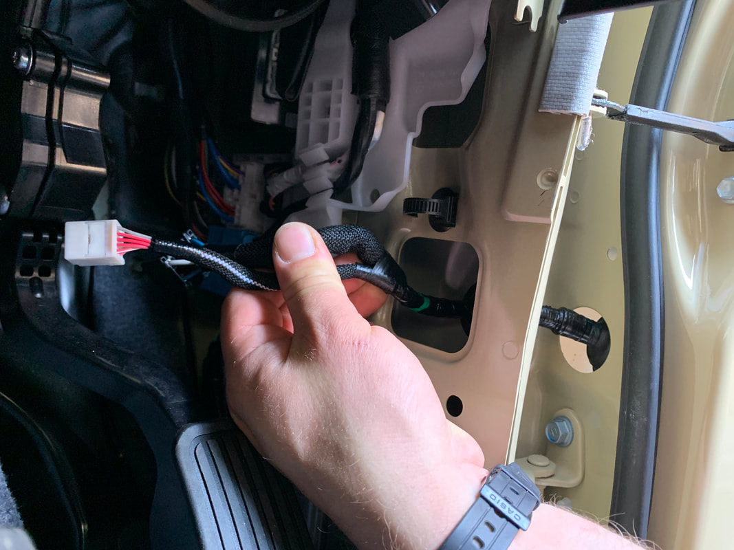
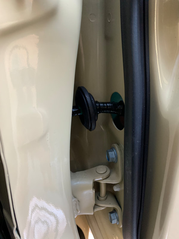
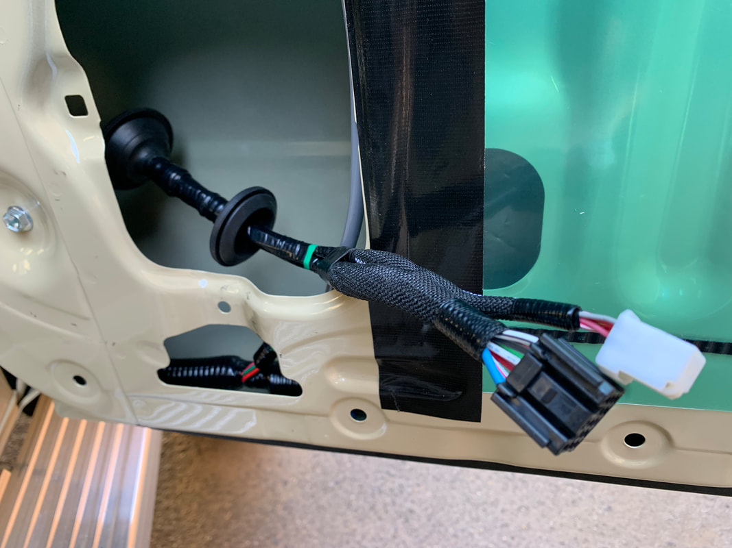
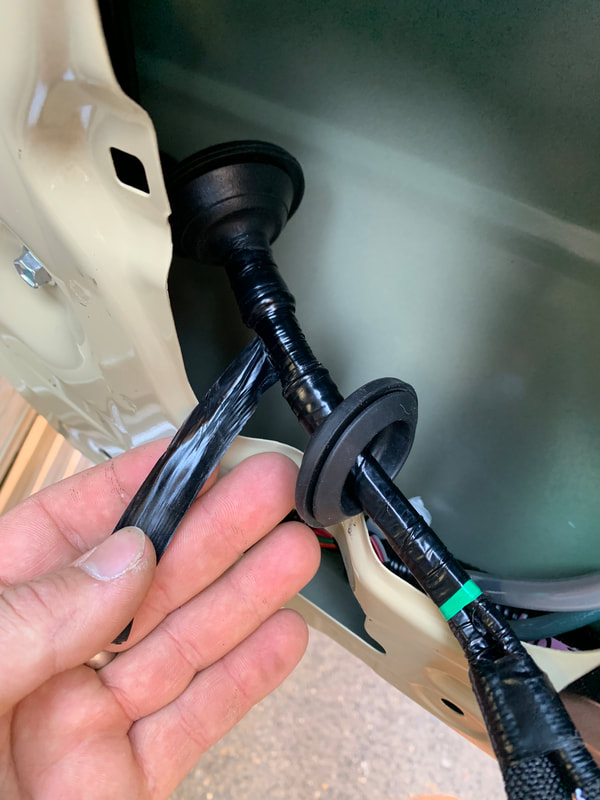
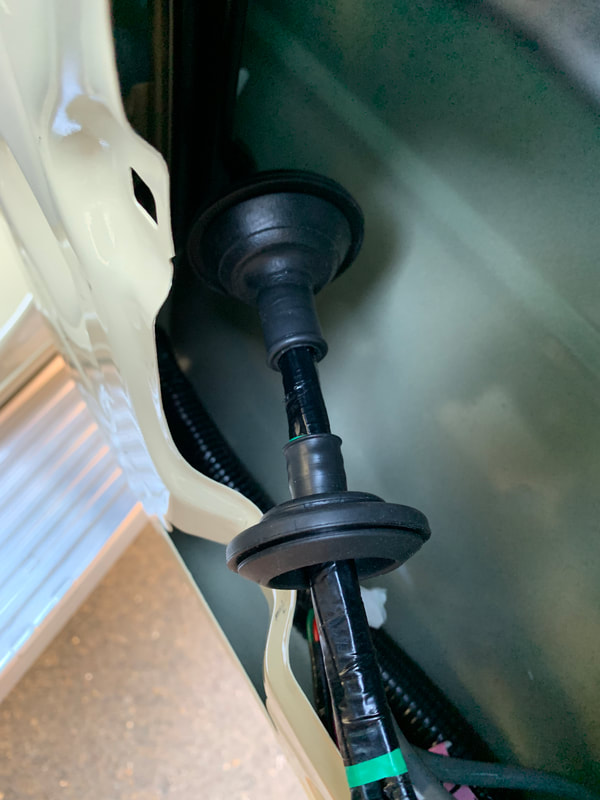
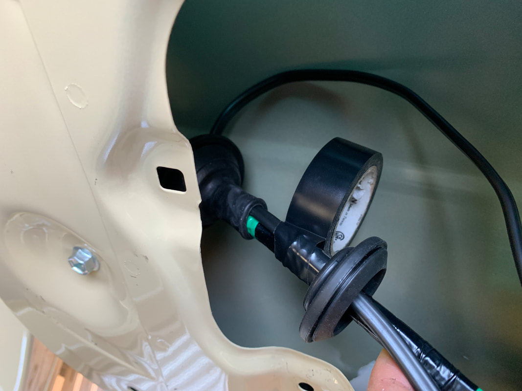
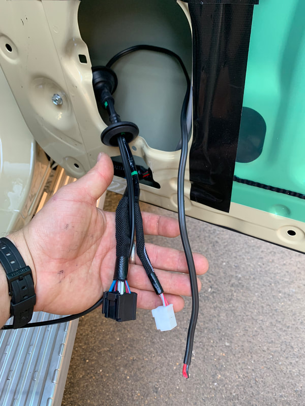
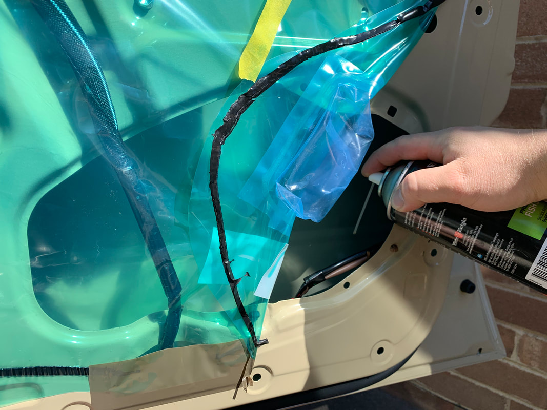
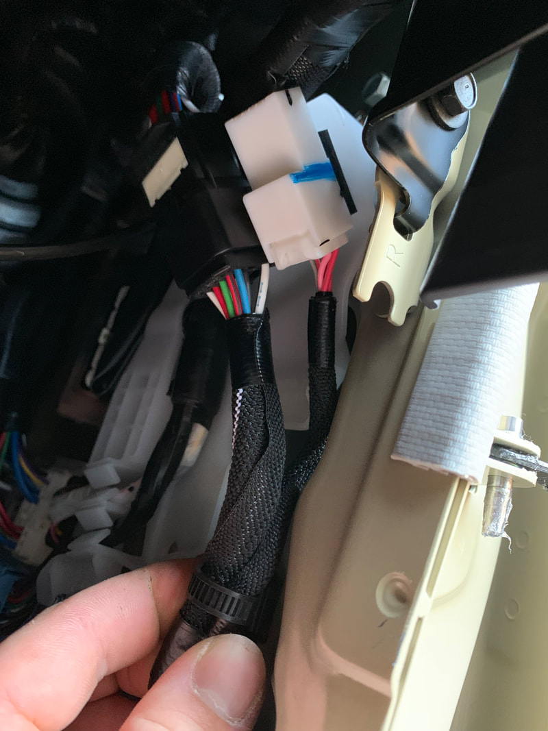
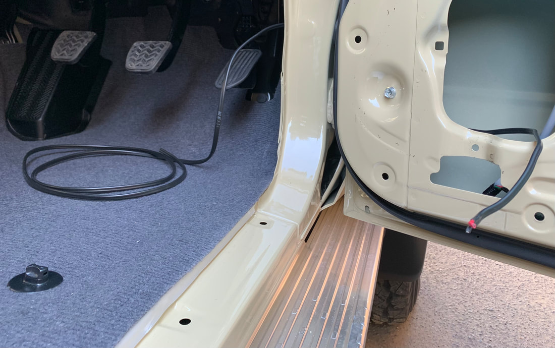
Below is a guide to routing your speaker cable through the factory wiring grommet.